
LAW OF FORCES
FREE BODY DIAGRAM:
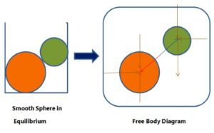
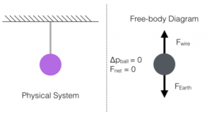
- A body may consists of more than one supports and elements. Each support or element can be isolated from the rest of the system by incorporating the net effect of the remaining system through a set of forces. The diagram of the isolated element or a portion of the body along with the net effects of the systems on it is called free body diagram.
- A diagram which shows the forces on the body free of other bodies is known as free body diagram.
- It shows the relative magnitude and direction of all forces acting upon an object in given situation.
- To study the equilibrium of a constrained body, we shall always imagine that we remove the supports and replace them by the reactions which they exert on the body.
Examples of free body diagram are given below:
COMPONENTS OF A FORCE:
When a single force acting on a body is represented by two forces acting in such a way that he effect produced by the two forces is same as that of the single force. Then these two forces are called component of the force. The system of breaking up the force is called resolution of force. The force which is broken in two parts is called the resolved force and the parts are called resolute.

In the figure, Fx and Fy are the components of the force F.
Generally a force is resolved into the following two types of components.
- Mutually perpendicular or orthogonal components.
- Non-perpendicular or Non-orthogonal components.
Mutually perpendicular or orthogonal components:
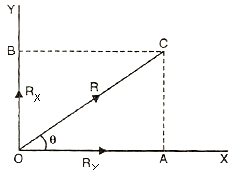
Let a force R be resolved in x and y directions makes an angle θ with the x axis. Let the force R be represented by line OC and components of the force R along X and Y directions be Rx and Ry. The components Rx and Ry are represented by line OB and OA respectively. Now complete the rectangle OACB.
Then,
OB = AC = Rx
OA = CB = Ry
Now from triangle OAC
AC = OC sin θ
Ry = R sin θ
and,
OA = CB
Rx = R cos θ
Non-perpendicular or Non-orthogonal components:
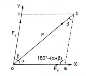
When a force is to be resolved along the two axes which are not mutually perpendicular, then the components of the force are called non-perpendicular components.
Force F makes an angle α and β with X and Y axis respectively.
The force F is to be resolved along oX and oY.
Complete the parallelogram oabc.
Then,
oa = cb = Fx
oc = ab = Fy
ob = F
∠aob = α
∠cob = ∠abo = β
∠oab = 180° – (α + β)
In triangle oab, applying sine rule,
[frac up=”Fx” down=”sin β”] = [frac up=”Fy” down=”sin α”] = [frac up=”F” down=”sin { 180° – (α + β) }”]
[frac up=”Fx” down=”sin β”] = [frac up=”Fy” down=”sin α”] = [frac up=”F” down=”sin (α + β)”]
Fx = {[frac up=”F sin β” down=”sin (α + β)”]}
and
Fy = {[frac up=”F sin α” down=”sin (α + β)”]}
RELATED VIDEOS: