
SHEAR FORCE is defined as the algebraic sum of all the vertical forces either to left or to the right hand side of the section.
BENDING MOMENT is defined as the algebraic sum of the moments of all the forces either to the left or to the right of a section.
SIGN CONVENTIONS:
- A clockwise shear will be taken as positive and an anti-clockwise shear will be taken as negative.
- A bending moment causing concavity upward will be taken as positive and will be called as Sagging Bending Moment.
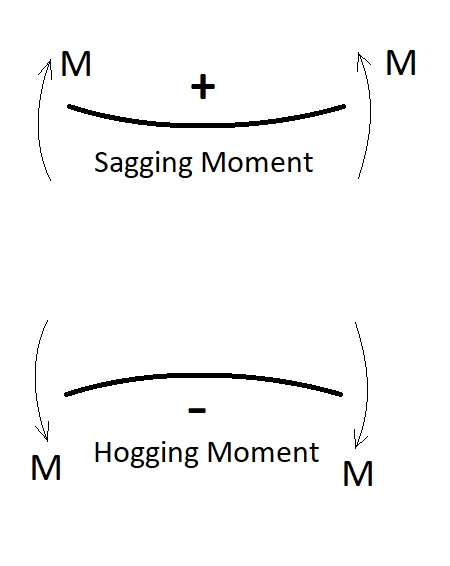
- A bending moment causing convexity upward will be taken as negative and will be called a Hogging Bending Moment.
SHEAR FORCE DIAGRAM:
It is a graphical representation of the variation of shear force along the length of the beam. The ordinate of the SFD at any section gives the value of the Shear Force at that section, due to the fixed load positions on the beam.
Shear Force Diagram will be Rectangular between POINT LOAD.
Shear Force Diagram will be Triangular between UNIFORMLY DISTRIBUTED LOAD.
Shear Force Diagram will be Parabolic between UNIFORMLY VARYING LOAD.
BENDING MOMENT DIAGRAM:
It is a graphical; representation of the variation of bending moment along the length of the beam. The ordinate of the BMD at any section gives the value of Bending Moment at that section, due to the fixed load positions on the beam.
Bending Moment Diagram will be Triangular between POINT LOAD.
Bending Moment Diagram will be Parabolic between UNIFORMLY DISTRIBUTED LOAD.
Bending Moment Diagram will be Hyperbolic between UNIFORMLY VARYING LOAD.
PROPERTIES OF SHEAR FORCE DIAGRAM:
- Shear Force Diagram consists of a rectangle, if the beam is loaded with point loads.
- Shear Force Diagram consists of inclined line for the portion on which uniformly distributed load is acting.
- Shear Force Diagram consists of parabolic curve for the portion over which triangular or trapezoidal load distribution is acting.
- Shear Force Diagram consists of cubic curve for the portion over which parabolic load distribution is acting.
- Shear Force does not change at the point of application of a couple.
PROPERTIES OF BENDING MOMENT DIAGRAM:
- Bending Moment Diagram consists of inclined lines for the beam loaded with point loads.
- Bending Moment Diagram consists of parabolic curve for the portion over which uniformly distributed load is acting.
- Bending Moment Diagram of cubic or third degree curve for the portion over which uniformly varying load is acting.
- Bending Moment Diagram consists of fourth degree curve if the load distribution is parabolic.
- Bending Moment is maximum where shear force is zero or changes sign.
- Bending Moment abruptly at the point of application of couple.
POINT OF CONTRAFLEXURE:
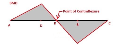
The bending moments of opposite nature always produce curvature of beams in opposite directions. In a beam if the bending moment changes sign at at point, the point itself having zero bending moment, the beam changes curvature at this point of zero bending moment and this point is called the point of contra flexure. So at a point of contra flexure the beam flexes in opposite direction. The point of contra flexure is called the point of inflexion or a virtual hinge.
USE OF SHEAR FORCE DIAGRAM AND BENDING MOMENT DIAGRAM:
- Every structure will try to resist the deformation by developing the internal resistance (Shear, Moment and/or Bending Moment). However, the properties of the body will decide how much resistance would be provided against loading.
- For example,
- A beam of concrete material has very high resistance to shear. It is however very weak in tension.
- A steel beam has high resistance in both shear as well as bending. However, it is very expensive when compared to concrete.
- Hence, while designing a beam of concrete we find the points of maximum SFD and BMD values. These values in turn give us the idea as to the kind of material and geometry we need to provide to resist deformation (or failure in general). Since, concrete is very cheap we try to provide as much of it as possible. However, it is weak in tension.

- Hence, for zones of maximum Bending Moment (which we find from BMD) we provide Steel reinforcements. We also find zones of maximum Shear Force (from SFD). If the shear force values surpass the concrete’s capacity (resistance) we provide steel shear stirrups in order to resist the additional shear.
- The same concept is applicable for columns as well.
RELATED VIDEOS: