
DERIVATION OF BENDING EQUATION
Let us assume that following beam PQ is horizontal and supported at its two extreme ends i.e. at end P and at end Q, therefore we can say that we have considered here the condition of simply supported beam.
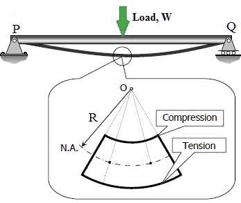
Once load W will be applied over the simply supported horizontal beam PQ as displayed above, beam PQ will be bending in the form of a curve and we have tried to show the condition of bending of beam PQ due to load W in the above figure.
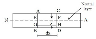
Now let us consider one small portion of the beam PQ, which is subjected to a simple bending, as displayed here in following figure. Let us consider two sections AB and CD as shown in following figure.
Neutral Layer
Now we have following information from the above figure.
AB and CD: Two vertical sections in a portion of the considered beam
N.A: Neutral axis which is displayed in above figure
EF: Layer at neutral axis
dx = Length of the beam between sections AB and CD
Let us consider one layer GH at a distance y below the neutral layer EF. We can see here that length of the neutral layer and length of the layer GH will be equal and it will be dx.
Original length of the neutral layer EF = Original length of the layer GH = dx
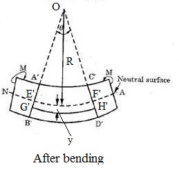
Now we will analyze here the condition of assumed portion of the beam and section of the beam after bending action and we have displayed here in following figure.
Neutral Surface
As we can see here that portion of the beam will be bent in the form of a curve due to bending action and hence we will have following information from above figure.
Section AB and CD will be now section A’B’ and C’D’
Similarly, layer GH will be now G’H’ and we can see here that length of layer GH will be increased now and it will be now G’H’
Neutral layer EF will be now E’F’, but as we have discussed during studying of the various
assumptions made in theory of simple bending, length of the neutral layer EF will not be changed.
Length of neutral layer EF = E’F’ = dx
A’B’ and C’D’ are meeting with each other at center O as displayed in above figure
Radius of neutral layer E’F’ is R as displayed in above figure
Angle made by A’B’ and C’D’ at center O is θ as displayed in above figure
Distance of the layer G’H’ from neutral layer E’F’ is y as displayed in above figure
Length of the neutral layer E’F’ = R x θ
Original length of the layer GH = Length of the neutral layer EF = Length of the neutral layer E’F’ = R x θ
Length of the layer G’H’ = (R + y) x θ
As we have discussed above that length of the layer GH will be increased due to bending action of the beam and therefore we can write here the following equation to secure the value of change in length of the layer GH due to bending action of the beam.
Change in length of the layer GH = Length of the layer G’H’- original length of the layer GH
Change in length of the layer GH = (R + y) x θ – R x θ
Change in length of the layer GH = y x θ
Strain in the length of the layer GH = [frac up=”Change in length of the layer GH” down=”Original length of the layer GH”]
Strain in the length of the layer GH = [frac up=”y x θ” down=”R x θ”]
Strain in the length of the layer GH = [frac up=”y” down=”R”]
As we can see here that strain will be directionally proportional to the distance y i.e. distance of the layer from neutral layer or neutral axis and therefore as we will go towards bottom side layer of the beam or towards top side layer of the beam, there will be more strain in the layer of the beam.
At neutral axis, value of y will be zero and hence there will be no strain in the layer of the beam at neutral axis.
According to Hooke’s Law, within elastic limit, stress applied over an elastic material will be directionally proportional to the strain produced due to external loading and mathematically we can write above law as mentioned here.
Stress = E. Strain
Strain = [frac up=”Stress ” down=”E”]
Strain = [frac up=”σ” down=”E”]
Where E is the Young’s Modulus of elasticity of the material
Let us consider the above equation and putting the value of strain secure above, we will have following equation as mentioned here.
[frac up=”σ” down=”E”] = [frac up=”y” down=”R”]
σ= [frac up=”y” down=”R”] x E
Therefore, bending stress on the layer will be given by following formula as displayed here
We can conclude from above equation that stress acting on layer of the beam will be directionally proportional to the distance y of the layer from the neutral axis.
MOMENT OF RESISTANCE:
As we have discussed that when a beam will be subjected with a pure bending, layers above the neutral axis will be subjected with compressive stresses and layers below the neutral axis will be subjected with tensile stresses.
Therefore, there will be force acting on the layers of the beams due to these stresses and hence there will be moment of these forces about the neutral axis too.
Total moment of these forces about the neutral axis for a section will be termed as moment of resistance of that section.
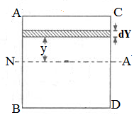
As we have already assumed that we are working here with a beam having rectangular cross-section and let us consider the cross-section of the beam as displayed here in following figure.
Figure
Let us assume one strip of thickness dy and area dA at a distance y from the neutral axis as displayed in above figure.
Let us determine the force acting on the layer due to bending stress and we will have following equation
dF = σ x dA
Let us determine the moment of this layer about the neutral axis, dM as mentioned here
dM = dF x y
dM = σ x dA x y
dM = [frac up=”E” down=”R”] x y x dA x y
dM = [frac up=”E” down=”R”] x y2 . dA
Total moment of the forces on the section of the beam around the neutral axis, also termed as moment of resistance, could be secured by integrating the above equation and we will have
dM = [frac up=”E” down=”R”] x y2 . dA
M = [frac up=”E” down=”R”] ∫ y2 . dA
I = ∫ y2 . dA
M = [frac up=”E” down=”R”] x I
[frac up=”M” down=”I”] = [frac up=”E” down=”R”]
Let us consider the above equation of moment of resistance and equation that we have secured for bending stress in case of bending action; we will have following equation which is termed as bending equation or flexural formula of bending equation.
[frac up=”MR” down=”IN.A“] = [frac up=”σb” down=”y”] = [frac up=”E” down=”R”]
RELATED VIDEOS: