
EXPERIMENT
OBJECTIVE:
To determine the bending stress of simply supported subjected to concentrated load at the center..
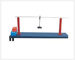
APPARATUS REQUIRED:
- Beam Apparatus
- Bending Fixture
- Vernier Caliper
- Meter Rod
- Test Piece
- Pan
- Weight
THEORY:
If a beam is simply supported at the ends and carries a concentrated load at its centre, the beam bends concave upwards. The distance between the original position of the beam and its position after bending at different points along the length of the beam , being maximum at the centre in this case. This difference is known as Deflection.
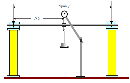
In this particular type of loading the maximum amount of deflection (𝛿) is given by the relation,
𝛿 = [frac up=”Wl3” down=”48EI”]
or E = [frac up=”Wl3” down=”48𝛿I”]
where,
W = Load acting at the centre, N
l = Length of the beam between the supports, mm
E = Young’s modulus of material of the beam, [frac up=”N” down=”mm2“]
I = Moment of inertia of the cross-section of the beam, about the neutral axis, mm4
BENDING STRESS:
As per bending equation:
[frac up=”M” down=”I”] = [frac up=”σb” down=”y”]
where,
M = Bending moment, N-mm
I = Moment of inertia, mm4
σb = Bending stress, [frac up=”N” down=”mm2“]
y = Distance of the top fiber of the beam from the neutral axis.
PROCEDURE FOR BEND TEST:
- Adjust the cast iron blocks along the bed so that they are symmetrical with respect to the length of the bed.
- Place the beam on the knife edges on the blocks so as to project equally beyond each knife edge.
- Note the initial reading of Vernier scale.
- Add a weight and again note the reading of the Vernier scale.
- Go on adding weight and take the reading till you have minimum six readings.
- Find the deflection in each case by subtracting the initial reading of Vernier scale.
- Draw a graph between load (W) and deflection (𝛿). On the graph choose any two convenient points and between these points find the corresponding values of W and 𝛿. Putting these values in the relation, E = [frac up=”Wl3” down=”48 EI”] calculate the value of E.
- Calculate the bending stresses for different tools using relation, σb = [frac up=”M.y” down=”I”].
OBSERVATIONS:
Record the following data:
Width of the beam, b = ….. mm (for rectangular cross-section)
Depth of the beam, d = ….. mm
Diameter of the beam, D = …. mm (for circular cross-section)
Moment of inertia for rectangular section = [frac up=”bd3” down=”12″] = ….. mm4
Moment of inertia for circular section = [frac up=”π.d4” down=”64″] = ….. mm4
Initial reading of the Vernier = ….. mm
OBSERVATION TABLE:
| S. No. | LOAD, W (N) |
BENDING MOMENT, M = [frac up=”Wl” down=”4″] (N-mm) |
BENDING STRESS, σb = [frac up=”M.y” down=”I”] ([frac up=”N” down=”mm2“]) |
DEFLECTION, 𝛿 = [frac up=”Wl3” down=”48EI”] (mm) |
YOUNG’S MODULUS OF ELASTICITY, E = [frac up=”Wl3” down=”48𝛿I”] ([frac up=”N” down=”mm2“]) |
PRECAUTIONS FOR BEND TEST:
- Make sure that the beam and load are placed at the proper positions.
- The cross-sections of the beam should be large.
- Note down the reading of the Vernier scale carefully.
RELATED VIDEOS FOR BEND TEST: